End-to-end Build Log: Raspberry Pi 5 touch Console + ESP32-S3-BOX Voice Assistant
End-to-end Build Log: Raspberry Pi 5 touch Console + ESP32-S3-BOX Voice Assistant
By Daniel Rod, Accredited Specialist, Family Law
Welcome to this exciting end-to-end build log where we’ll guide you through creating a Raspberry Pi 5 Touch Console integrated with an ESP32-S3-BOX Voice Assistant. This project combines the computational power of the Raspberry Pi 5 with a sleek touchscreen interface and a versatile voice assistant module, resulting in a powerful tool for home automation enthusiasts. Whether you’re looking to control your smart home devices with a tap or a spoken command, this setup offers both flexibility and functionality. Plus, with the addition of a local voice assistant, your privacy remains intact as no data leaves your network. Let’s dive into this step-by-step journey and bring this innovative project to life!
1. Bill of Materials
Before we start assembling anything, let’s gather all the components needed for this project. Here’s a detailed breakdown of everything you’ll require, along with some insights into why each item is essential and what to consider when sourcing them.
| Qty | Item | Notes |
|---|---|---|
| 1 | Raspberry Pi 5 (4 GB/8 GB) | The heart of our setup, the Raspberry Pi 5 is the latest model (as of 2025) and comes in 4 GB or 8 GB RAM variants, both of which are suitable for this project. A 27 W USB-C PSU is recommended to ensure stable power delivery, especially since we’ll be powering a touchscreen alongside the Pi’s processing demands. This ensures your system won’t stutter under load. |
| 1 | Freenove 5-inch 800 × 480 IPS capacitive DSI display | This compact 5-inch touchscreen boasts an 800 × 480 resolution and connects directly to the Pi via its DSI port. It’s driver-free, meaning no extra software is needed for basic operation, and supports 5-point capacitive touch for smooth interaction. The IPS panel offers vibrant colors and wide viewing angles, making it perfect for a console you might place anywhere in your home. |
| 1 | 32 GB (or larger) micro-SD card | Flashed with Home Assistant OS, this card serves as the storage for your operating system and data. A 32 GB card is the minimum, but if you plan to log extensive device states or run additional services, consider stepping up to 64 GB or even 128 GB for extra breathing room. Speed class 10 cards are ideal for faster boot times. |
| 1 | ESP32-S3-BOX dev-kit | This development kit is packed with features: Wi-Fi and Bluetooth Low Energy (BLE) for connectivity, dual microphones for voice input, a 2.4″ IPS touchscreen for direct interaction, an IR transmitter/receiver for controlling legacy devices, and PMOD headers for future expansions. In this project, it’s our voice assistant powerhouse, adding hands-free control to the mix. |
| – | Misc hardware | This includes 4 short + 4 long M2.5 brass standoffs, 8 M2.5 screws, a 15 cm DSI ribbon cable, and a USB-C cable. The short standoffs secure the display, while the long ones mount the Pi, ensuring proper spacing. The DSI ribbon connects the display to the Pi, and the USB-C cable powers the whole setup. These small pieces are crucial for a sturdy and functional assembly. |
When sourcing these items, opt for reputable vendors to ensure compatibility and reliability. If you’re new to DIY electronics, don’t fret—each component is straightforward to work with, and I’ll walk you through every step to make this process as smooth as possible.
2. Hardware Assembly
Now that we have our components, it’s time to put them together. Assembling the hardware is a satisfying hands-on process, but it requires care—especially with delicate parts like the DSI ribbon cable. Let’s break it down into manageable steps.
2.1 Mounting the Display
Here’s how to securely attach the Freenove display to the Raspberry Pi 5:
- Fit the four short standoffs to the rear of the Freenove PCB (see red arrows above). Start by screwing the four short M2.5 brass standoffs into the mounting holes on the back of the display’s printed circuit board. These provide a stable base and create just enough space to avoid pressure on the display’s electronics. If you have a diagram handy, the red arrows will point you to the exact spots—otherwise, they’re typically at the corners.
- Insert the 15 cm DSI ribbon into the panel’s FFC with contacts facing down, lock the latch, and gently tug to confirm retention. Take the DSI ribbon cable and carefully slide it into the display’s Flexible Flat Cable (FFC) connector. Ensure the shiny contacts face downward toward the PCB, then press the latch down to lock it in place. Give it a light tug to make sure it’s secure—loose connections here can lead to display issues later.
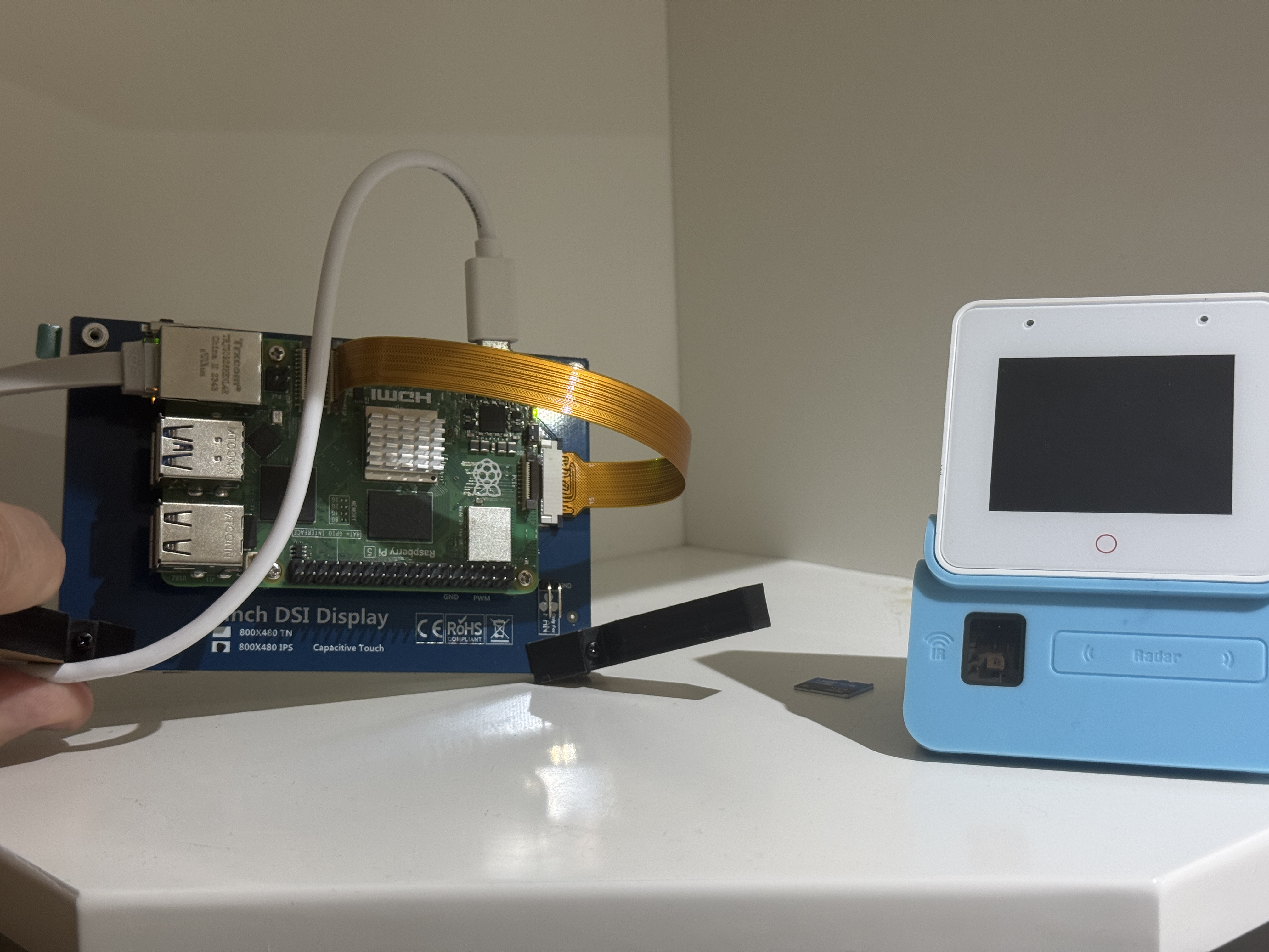
- Seat the Raspberry Pi 5 on the standoffs, align the ribbon with the Pi’s DSI-0 socket and latch. Position the Pi over the standoffs so its mounting holes line up. Then, take the other end of the DSI ribbon and insert it into the Pi’s DSI-0 port (check your Pi’s labeling). Again, ensure the contacts face the right direction—usually toward the board—and secure the latch. This direct connection is what makes the DSI display so seamless.
- Screw the Pi down, then replace the four long standoffs to give clearance for HDMI & GPIO headers. Use the 8 M2.5 screws to fasten the Pi to the short standoffs, then attach the four long standoffs to the Pi’s mounting holes. These longer standoffs lift the Pi slightly, ensuring that ports like HDMI and GPIO remain accessible and that airflow isn’t obstructed—a small but critical detail for heat management.
Tip: For portrait orientation rotate in software—do not twist the ribbon. Twisting the DSI cable might seem like a quick fix to change the display’s orientation, but it risks damaging the cable or causing display glitches. Instead, we’ll adjust this in the software settings later, keeping everything neat and functional.
2.2 Power-up & First-boot Checks
With the hardware assembled, let’s power it up and verify everything’s working:
- Edit the config.txt file. Before inserting the micro-SD card into the Pi, access its
/boot/firmware/config.txtfile on your computer and add this line:
# /boot/firmware/config.txt
dtoverlay=vc4-kms-v3d   # Enable KMS for DSI panel
This line activates Kernel Mode Setting (KMS) for the DSI display, telling the Pi’s graphics system how to handle the touchscreen. It’s a simple but essential tweak for proper display output.
- Save and
sudo reboot. Save the file, eject the SD card, insert it into the Pi, and connect the USB-C power supply. The back-light should illuminate ~2 seconds after power-on, a reassuring sign that the display is powered and the DSI connection is solid. If it doesn’t light up, double-check your ribbon cable connections and the config tweak.
This initial boot lets you confirm the hardware is talking to each other correctly before we load the software.
3. Flashing home Assistant Os
Next, we’ll install Home Assistant OS, an open-source platform that turns your Raspberry Pi into a smart home hub capable of controlling lights, thermostats, and more. Here’s how to get it onto your micro-SD card:
- Launch Raspberry Pi Imager. Download and open the Raspberry Pi Imager tool on your computer—it’s a user-friendly way to write operating systems to SD cards.
- Operating System → Home Assistant OS → Raspberry Pi 5 (64-bit). In the imager, select the Home Assistant OS option tailored for the Raspberry Pi 5’s 64-bit architecture. This ensures optimal performance for our setup.
- Select the SD card under Storage. Pick your micro-SD card from the list—double-check it’s the right device to avoid overwriting something else!
- (Optional) open the ⚙️ menu to set hostname, Wi-Fi, locale (en-AU) and enable SSH. Click the gear icon for advanced settings. Here, you can name your device (e.g.,
homeassistant), enter your Wi-Fi details for wireless connectivity, set your region (likeen-AUfor Australia), and enable SSH for remote command-line access. These tweaks streamline setup and troubleshooting. - Click Write, eject, insert, power the Pi. Hit Write to flash the OS onto the card. Once done, safely eject it, pop it into the Pi’s SD slot, and plug in the power. After ~3 minutes, browse to
http://homeassistant.local:8123(or the Pi’s IP if mDNS fails) to complete onboarding via the web interface.
This process sets up the foundation for our smart console. If the display or network doesn’t kick in, ensure your config.txt edit from earlier is correct and your Wi-Fi details are accurate.
4. Setting-up the ESP32-S3-BOX
The ESP32-S3-BOX brings voice control to our project, and setting it up involves preparing its development environment and flashing its firmware. Let’s get it ready.
4.1 Tool-chain & Sdk
Here’s how to configure the ESP32-S3-BOX from your computer:
git clone --recursive https://github.com/espressif/esp-box.git
cd esp-box
./install.sh                     # installs ESP-IDF v5.x
. export.sh                      # add IDF tools to shell
idf.py set-target esp32s3
idf.py build
idf.py -p /dev/ttyUSB0 flash monitor
- Step-by-step explanation: First, clone the
esp-boxrepository from GitHub—it’s packed with the code and tools we need. Navigate into the folder, then runinstall.shto set up the ESP-IDF (Espressif IoT Development Framework), version 5.x, which is the backbone for ESP32 development. Next,export.shadds the IDF tools to your terminal session. Set the target toesp32s3(the chip in the BOX), build the firmware withidf.py build, and finally flash it to the BOX via USB (adjust/dev/ttyUSB0to your port, likeCOM3on Windows) while monitoring the output. - Testing it out: The board reboots into the built-in voice-assistant demo—say “Hi Espressif!” to test the far-field mics. If it responds, you’re golden! If not, check your USB connection and drivers.
4.2 Ota-ready Firmware
To make future updates easier, copy build_esp32s3-box.bin to Home Assistant’s /config/www/ folder so you can update the BOX later with a simple HTTP request. This Over-The-Air (OTA) capability means you won’t need to plug it in again for firmware tweaks—just push updates wirelessly from Home Assistant.
5. Integrating the Box with home Assistant
Now, let’s connect the ESP32-S3-BOX to Home Assistant for seamless voice control. Here’s an example automation to get you started:
# Example automation: pause media when you say "pause music"
alias: Voice - pause media
trigger:
  - platform: state
    entity_id: sensor.esp32s3_box_last_command
    to: "pause music"
action:
  service: media_player.media_pause
  target:
    entity_id: media_player.living_room
mode: single
This YAML snippet pauses your living room media player when you say “pause music” to the BOX. It’s a simple demo, but you can craft automations for lights, locks, or anything else in your smart home.
- Integration steps: In Home Assistant, go to Settings → Devices & Services → Add Integration, select ESPHome, and point it at the BOX’s mDNS address (e.g.,
esp32s3-box.local). Once connected, the mic level, wake-word state, and touch buttons appear as entities you can monitor or use in automations. This ties the voice assistant into your smart home ecosystem effortlessly.
6. Adding Willow for Local, Private Voice Commands
For privacy-conscious users, Willow offers a fully local voice assistant with sub-500 ms response times. Here’s how to add it:
- Run the Willow Application Server on the Pi:
docker run --detach --name=willow-was \
--pull=always --network=host --restart=unless-stopped \
--volume=was-storage:/app/storage \
ghcr.io/heywillow/willow-application-server
- This command uses Docker to pull and run the Willow Application Server (WAS) in the background, ensuring it restarts unless you stop it. The
--network=hostflag links it to the Pi’s network, and the volume keeps settings persistent. - Obtain the Pi’s IP:
ip route get 1.1.1.1 | grep -oP 'src \K\S+'
Run this to find your Pi’s IP address (e.g., 192.168.1.100).
- Configure and flash: Open
http://<IP>:8502in a browser, set your Wi-Fi and WAS URL, then flash the ESP32-S3-BOX via Web-USB following the prompts. - Add to Home Assistant: Install the Willow Voice Assistant integration in Home Assistant and point it to the WAS for fast, offline voice control.
Willow keeps your voice data local, making it a standout feature for privacy and speed.
7. Touch-optimised Lovelace Dashboard
Because the display is 800 × 480, a compact resolution, we’ll optimize Home Assistant’s Lovelace dashboard for touch. Use narrow vertical-stack cards to fit content neatly, and set the HA theme font-scale to 110% for better readability. The IPS panel’s wide viewing angle makes it ideal for bedside or kitchen controllers—places where you might glance at it from odd angles. Consider designing a custom dashboard with big, tap-friendly buttons for quick access to key controls.
8. Future Ideas
Your console is up and running, but why stop there? Here are some creative enhancements:
| Idea | Description |
|---|---|
| Presence-aware widgets | Use the BOX’s Bluetooth scanning to publish occupancy to HA. Imagine lights turning on as you enter a room, all based on detecting your phone! |
| IR bridge | Train the BOX’s IR LED/receiver to control legacy appliances. Capture IR codes from your TV remote and use voice commands to switch channels or adjust volume. |
| Edge ML | Deploy keyword-spotting or person-detection models with ESP-DSP. Run machine learning on the BOX itself for custom wake words or security alerts, no cloud required. |
| Pi Camera overlay | Add a Pi 5 camera and picture-in-picture the feed on the touch UI. Perfect for checking the front door or keeping an eye on a pet from your console. |
These ideas can take your project to the next level, tailoring it to your unique needs.
There you have it—a fully functional Raspberry Pi 5 Touch Console with an ESP32-S3-BOX Voice Assistant! This build log has walked you through every step, from gathering parts to dreaming up future upgrades. Enjoy your new smart home controller, and feel free to tweak it to make it your own!
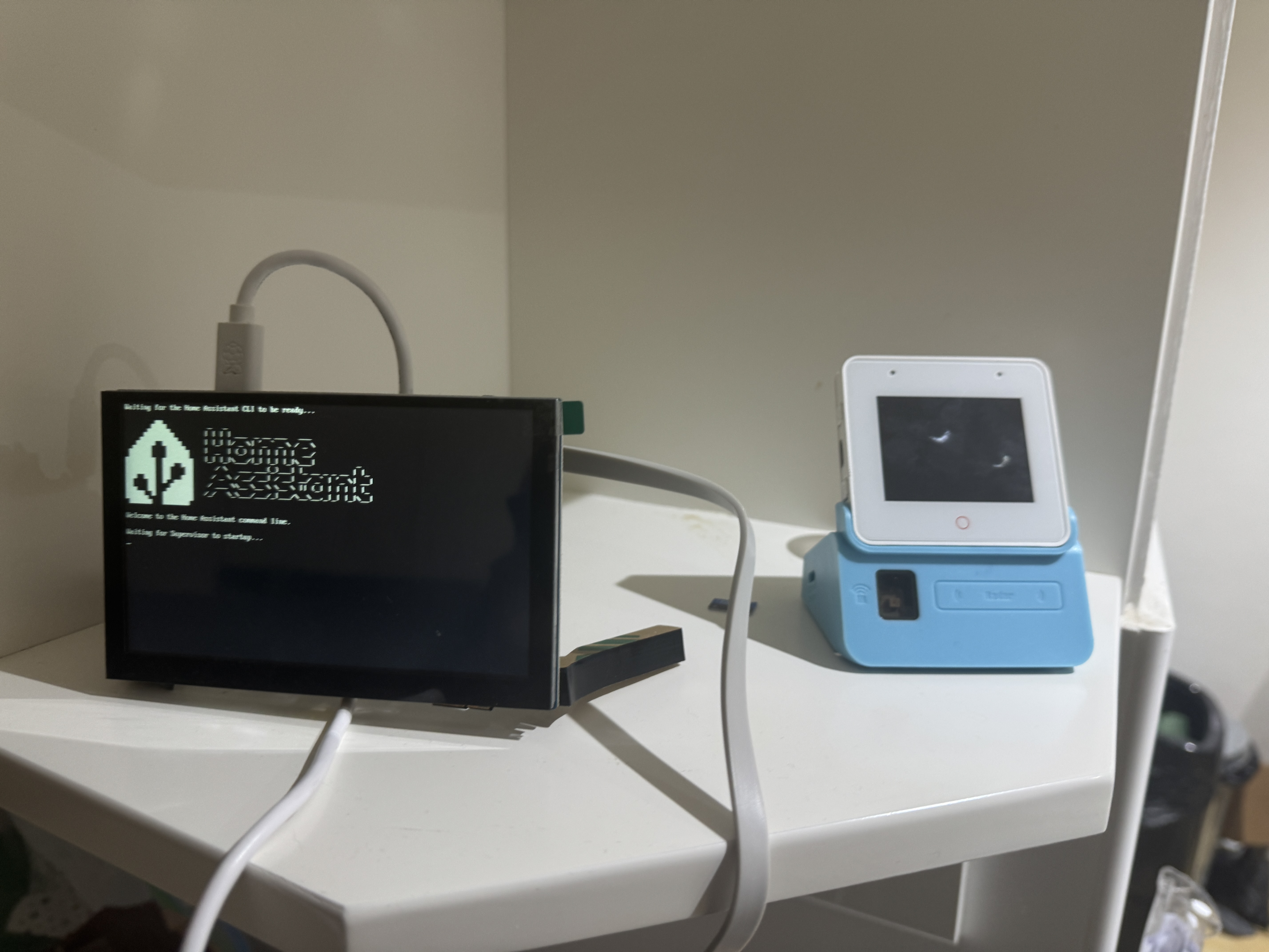
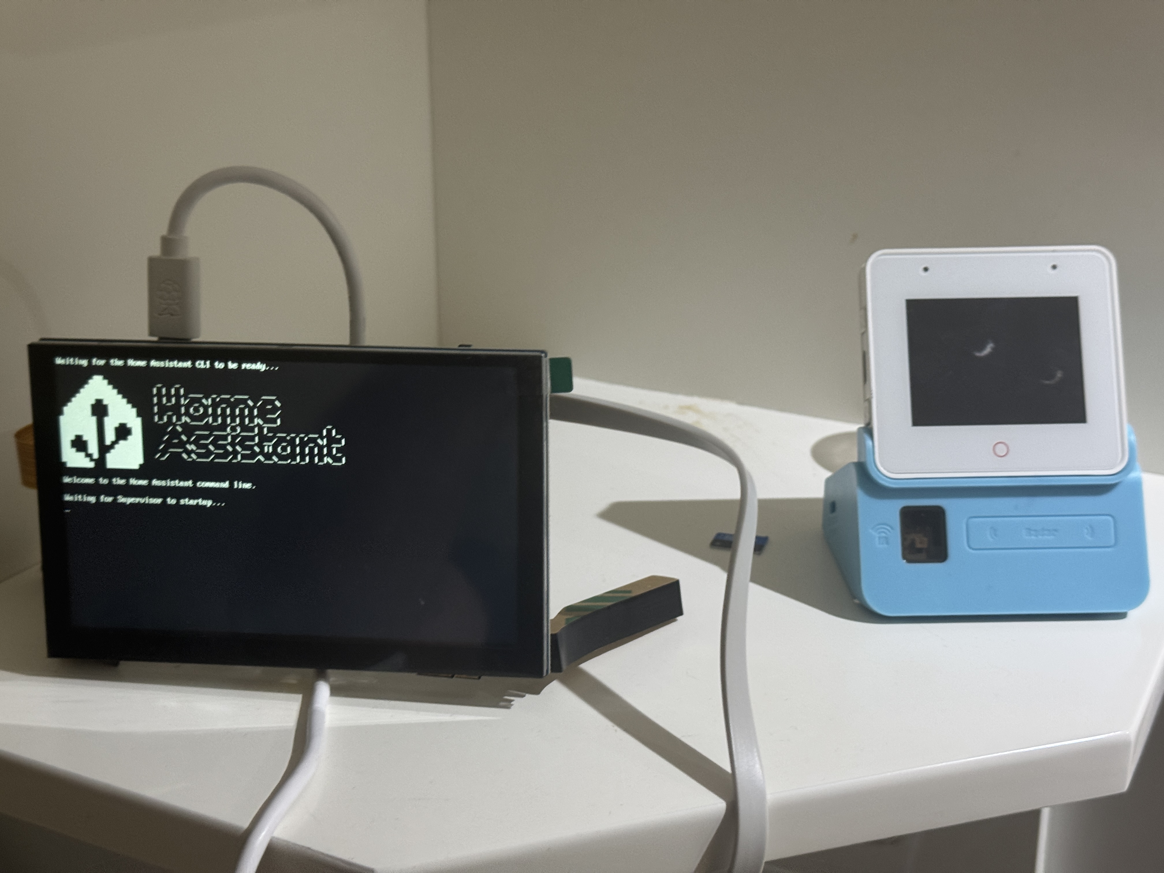
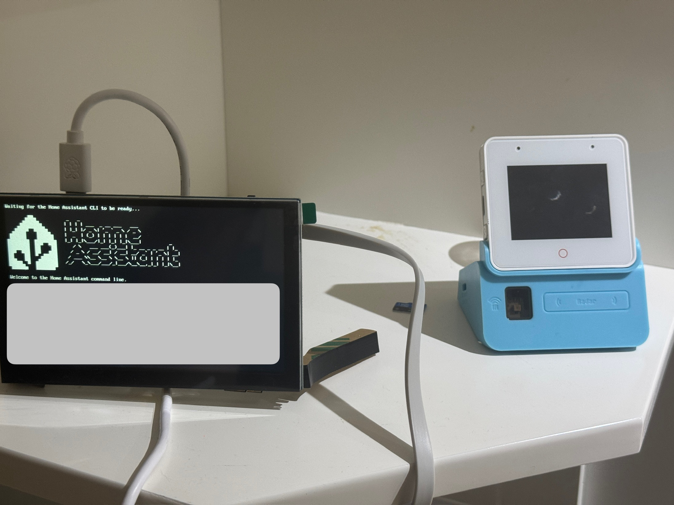
Final product below!